Literature Archives - Level 3 Inspection

Archive for the ‘Literature’ Category

Blocker Door Inspection

Level 3 Inspection Serves AAR PMA Group
Through the Complete Product Modernization Cycle
Advanced technologies and new process capabilities in expert services support market demands for improved replacement parts in the jet engine industry.
Companies who are engaged in commercial aviation replacement parts production under FAA Parts Manufacturer Approval (PMA) often need to capture and reproduce complex part geometry with higher accuracy and even tighter tolerances than the original manufactured part.
For some suppliers, these strict requirements can be insurmountable. For PMA companies such as AAR, the ability to meet these requirements with technical services support from Level 3 Inspection, has become a comparative advantage that leads to expanded business. This Article illustrates an unusual “full circle” approach from reverse engineering through first article inspection and into production with production sampling inspection.
AAR, founded in 1951, is a worldwide aviation support company offering services that include MRO, supply chain, structures and systems, and sales and leasing. Their product development center is in greater Atlanta and they employ many design engineers who use traditional measurement technologies and current CAD programs to produce the parts their airline customer’s demand.
Level 3 Inspection combines a depth of aerospace expertise with state-of-the-art 3D White Light Scanning (WLS) and advanced geometric processing technologies to reverse engineer, quality inspect, design optimize and then validate turbine engine components and assemblies.
AAR originally worked with the technical professionals who founded Level 3 Inspection (“L3I”) www.level3inspection.com to reverse engineer a complex jet engine thrust reverser part without any existing CAD data.  After the new CAD models were created from OEM part scans, and the investment casting process optimized to produce the first parts, AAR also requested the First Article Inspection of the new produced parts to be performed by L3I. Production inspection is anticipated to happen as soon as the first lot of new PMA parts is available.

Beyond CMM and CAD

AAR provided L3I with five sample OEM-produced parts that needed to be accurately 3D digitized then averaged into a nominal CAD model.  In the past, AAR would have used their own touch-point CMM to gather the data and then build the model in CAD software from averaged data.  This particular part, however, was a blocker door for a turbine engine made up of complex, organic shapes.  The part would have been difficult or impossible to capture and recreate using a CMM point-data and CAD software.
The geometry for the part was very challenging,” said Paul Ilenda, Manager of Outside Engineering Services for AAR’s PMA Group.  “There were no flat surfaces and seemingly many irregularities from part to part.”
Level 3 Inspection was uniquely qualified to do the work because of its expertise in aerospace parts digitizing using a White Light Scanner for data capture and then comprehensive post-processing of the scan files with software for aligning, averaging and modeling the large data sets generated by the scanner.  3D WLS is particularly suited to MRO projects because it enables engineers to quickly capture and process the average or optimal shape with tremendous accuracy, within 0.0005 inches (13 microns).
Using automated features in post processing software, Level 3 Inspection created a new average dataset From multiple 3D scans of the five AAR sample parts.
“The ability to create an average data set automatically saved a large amount of time and eliminates the guess work of manual averaging,” says Scott McAfee, Level 3 Inspection’s Vice President of Engineering.  “It provides a complete visualized data set rather than just specific dimensions.  This aids tremendously in the highly iterative CAD model-development process.”
McAfee took the sections taken from the average model and imported them into CAD/CAM software to create the nominal model.  From the nominal model, a detailed dimensional report, including GD&T, was created in their software.  The software then was used to batch-process report results from the original five data sets.

New capabilities and credibility

The final steps for Level 3 Inspection were converting the optimized CAD model to CATIA, and delivering the supporting dimensional package to AAR.  The entire process of digitally reconstructing the complex part, averaging the data for the samples and providing trend reports, took about two weeks.  McAfee estimates that Level 3 inspection’s ability to automate saved about a week of time or 33%.
Level 3 Inspection used software to compare the CAD model  to each of the scanned sample parts provided by AAR.
Perhaps even more important than time savings for AAR were the new capabilities that L3I brought to the table and the fact that the outsourcing freed AAR to concentrate on other projects.
“It was difficult for us to understand the intended surface geometry given the limited data from our touch-point CMM,” says AAR’s Ilenda.  “Level 3 Inspection was able to use the combination of the White Light Scanner and post processing software to provide much more comprehensive detail.  A big additional benefit was that we freed up resources internally to work on other projects while L3I was performing the reverse engineering.”
Ilenda says that the ability to tap into part digitization capabilities through Level 3 Inspection will help AAR create a greater competitive advantage in the MRO market.
“Because this was a difficult part to reverse engineer, it adds credibility to our PMA team and sets us apart from companies unwilling to take on such challenges,” says Ilenda.  “We are also able to provide a quality part to our customers at substantial savings over OEMs.”

Automation saves time and tedium

Once data was collected for the five samples, it was aligned in the post processing software.
Level 3 Inspection used software to align data sets from five AAR sample parts digitized with a 3D White Light Scanner.
Level 3 positioned the multiple scans into alignment, as the color plots graphically show any alignment problems for each scan, making it simple to identify alignment and/or part geometry deviations.
Sections from the average model were used to develop the nominal CAD model
Level 3 Inspection used software to compare the CAD model to the average data set created from each of the scanned sample parts provided by AAR.
“The ability to batch-process the reports on the five individual parts using the average report as a template was tremendously efficient,” says McAfee.  “It enabled us to compare trends from the five individual OEM parts to the average data set, which added credibility and supported AAR with plenty of information to use directly for PMA approval.”
Computer Aided Inspection Closes the Loop
Several months after their Blocker Door part was produced in the investment casting manufacturing process, AAR again called on Level 3 Inspection to perform the First Article Inspection. This critical step in part production and PMA approval was necessary to confirm that the multiple manufacturing steps were optimized to consistently produce quality parts for use in aircraft.
Level 3 Inspection used software to compare the CAD model  to the first article sample in order to report dimensional information based on the part drawing requirements (CAD model is RED – WLS data is BLACK).
All of these detailed inspections and the positive results that were the inspection outcome from this FAI process gave AAR even greater confidence in the CAD model and the production process. Based on all of the top quality outcomes and consistent geometric conformance, production runs are now being ordered from the investment casting foundries.
Most recently, AAR asked L3I to provide a proposal for production inspection on some to be agreed statistical sampling basis of the hundreds of parts contracted to be produced over the coming months. Based on the observed degree of part consistency identified in the first lot, the part sampling rate for inspection may be reduced over subsequent lots of production parts.
Updates to this unusually complete, ‘full development cycle’ of reverse engineering through first article inspection through production inspection in the PMA marketplace will be made available through this publication and on L3I’s web site, www.level3inspection.com.
By performing another comprehensive 3D digitization, using the same White Light Scanning of the new produced part, and within the separate post processing software suite, comparing it to the previously produced CAD model, L3I was able to identify the casting process results accuracy and quality conformance.
Level 3 Inspection used software to compare the CAD model  to the first article sample in order to report surface deviations.
The ability to completely and accurately scan the part and make the digital comparison between scan file and CAD model, with the level of detail and dimensional tolerances built into the Computer Aided Inspection process makes this the ideal method for proving out the manufacturing process. Additionally, L3I was asked to make a comparison of the new produced part to the OEM parts for further proof and support in the PMA process. This PMA part to OEM part comparison was critical in the acceptance and approval process.
For further information about this particular application of modern manufacturing and quality engineering technologies or any other interest applying these services and tools to solve industrial and business problems, contact Level 3 Inspection at 888-4AS-9102 or sales@level3inspection.com

Aerospace Rigor in Orthopadic Implants

ARE YOU READY TO BUILD FIGHTER JET RIGOR INTO YOUR MEDICAL DEVICES…AND SAVE MONEY DOING IT?
“First rule in government spending: why build one when you can have two at twice the price?” – Contact, 1997
Sobered by the passage of comprehensive health care reform in March 2010, medical device companies understandably fear being at the mercy of nearly non-negotiable government contracts that emerge from politically-polarized debates.  Process and design engineers might be forgiven for doubting that now is the time for a seismic shift in product development.  Likewise, quality directors might be tempted to fall back on tried-and-almost-true inspection methods.
Time is money, and process is time!
True not only in the increasingly-competitive orthopedic industry, but all precision manufacturing.  In sober times, orthopedic manufacturers should investigate any opportunity to streamline their processes and save money.
As we offer our candid assessment of the current state of the orthopedic industry’s use of measurement and inspection in its design and manufacturing processes, Level 3 Inspection believes that the story of Pratt & Whitney’s F135 gas turbine engine offers several insights relevant to the medical device industry.

THE “WOW!” FACTOR – THE PRATT & WHITNEY F135

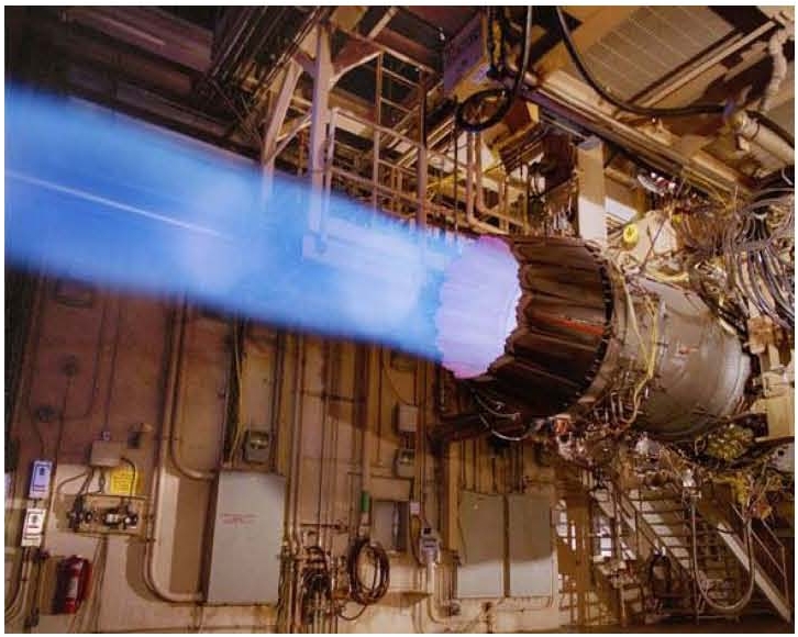
The story of the F135, developed for the F-35 Lightning II single-engine strike fighter, is so atypical of government spending programs as to nearly strain credulity.  Among the F135’s impressive roster of “mosts” and “firsts” is this gem: it’s the first military jet engine in history to be delivered both on time and under budget.
Assisted by Level 3 Inspection cofounder Scott T. McAfee and under competitive pressure, Pratt & Whitney fully implemented High-Resolution 3D White Light Scanning (WLS) and Computer Aided Inspection (CAI) in the early 2000s.  The F135 was the first gas turbine engine to be designed and built using WLS/CAI technology from the ground up – that is, from the early conceptual stages all the way through to durability testing.
Knowing the entire geometry of every component, via accurate and thorough WLS/CAI, was the way the F135 could be brought in on schedule and budget.  But the real “Wow!” factor emerges when we take a closer look at performance and durability.
The F135 is the most powerful gas turbine engine ever built, offering 43,000 pounds of thrust.  Says Bennett Croswell, VP of F119/F135 programs, “This is truly a historic accomplishment, not just for Pratt & Whitney and the F135 team, but really for all of military aviation.  This is the first time … that a production ready, stealthy, short take-off vertical landing capable aircraft has flown supersonic.”
In addition to being the most powerful jet engine ever built, the F135 is also the most durable.  Since the “wear” on an engine is a complex phenomenon that depends on throttle movement and acceleration/deceleration, the Air Force Technical Institute developed a unit of measurement called the Total Accumulation Cycle (TAC).  Service life is based on an estimate of how many TAC’s an engine can tolerate between overhauls.
The F135 test engine was run in conditions simulating flight at 30,000 ft. and Mach 1.5, with the turbine at 50°F above melting temperature and the high and low pressure turbine spools spinning at 100%.  “It ran and was then inspected.  There was no distress and no required maintenance,” says Croswell.
The targeted service life was 8000 TAC’s, but the initial service test went all the way to 8700 TAC’s.  Upon disassembly, the components showed no signs of breakdown.  As a result of the F135’s unprecedented triumph in durability, monies that would have been used to cover program overages (of which there were none!) are now being used to fund further durability testing for the U.S. Navy.
As Pratt’s competitors, Rolls-Royce and General Electric, have been unable to develop an operational alternative to the F135, Pratt is likely to remain the sole supplier of engines for the F-35 fighter – a market estimated at $100 billion.  That’s a compelling return on Pratt’s CAI investment of less than $5 million.
This incredible achievement was possible because Pratt & Whitney was able to know the entire surface geometry – not only of every vane and blade, but of every nut and bolt.  Level 3 Inspection’s founders were key players in P&W’s implementation of advanced WLS and CAI technologies, and L3I remains to this day a Pratt & Whitney Joint Venture Partner.

PARADIGM SHIFT
Our collaboration with Pratt & Whitney has generated a seven-step design paradigm that’s revolutionized aerospace, with P&W’s industry colleagues racing to catch up.

1.   Gather information through CAI.

2.   Study the data for problems, trends and surprises.
3.   Gain meaningful insights into process capabilities and limits.
4.   Revise design parameters to line up with realistic process limits.  Extravagantly tight tolerances are a self-defeating proposition … especially when regulatory agencies like the FDA get into the mix.

5.   Drive insights back into manufacturing to shrink process limits and create specific production measurement plans to track areas of concern vis-à-vis process capability and limits.
6.   Continue to gather data periodically.  Trust the data from advanced measurement techniques, and learn from what it tells you – good or bad.
7.   Expand the focus to tooling and other upstream processes in order to have more control sooner, and catch problems before they grow.

WHO WILL REVOLUTIONIZE ORTHOPEDICS?


STRATEGIC PARTNERS

By bolstering confidence in processes and products, joint venture partnerships with L3I have helped orthopedic customers to:
  • Phase out the antiquated practice of 100% inspection before their industry colleagues do
  • Reimagine industry standards for product safety, reliability, service life and durability
  • Drive new standards for regulatory compliance
Through CAI-facilitated design, L3I stands ready to partner with your firm in strategic cooperation, allowing you to:
  • Reduce time to market for new products by 25-50%
  • Reduce revision time for existing products by 55-85%
  • Solve engineering problems that have dogged your design team for years


TO IMPLEMENT FIGHTER JET RIGOR, HOW MUCH LESS ARE YOU WILLING TO SPEND?CONSIDER SOME OF THE REAL-WORLD EXAMPLES OF WAYS THAT L3I HAS SAVED ITS CLIENTS MONEY:

1.  One of L3I’s first orthopedic CAI contracts was an inspection of a new hip broach to the CAD and to a used broach.  L3I’s inspection report was used in legal defense in a class action lawsuit, showing that the issue was clearly not the fault of the implant or broach.  The strength of the technical inspection combined with the easily understood visualization were critical in allowing this client to mount a successful defense.  Through improved process confidence, L3I can help orthopedic companies reduce their legal exposure.

2.  This shoulder dome had been passed as dimensionally acceptable by the CMM in the manufacturing cell.  L3I gathered 1000 times more surface data than the CMM and created the best-fit sphere through the data, finding the part to be out of tolerance. A two-week correlation study was called and the metrology department was asked to be arbitrator.  After seeing 100% correlation between the 200 CMM data points and those same points in the 200,000 WLS data, but realizing that the CMM data points overlooked a ring-shaped anomaly on the part, metrology stated that WLS/CAI was “clearly superior to CMM”.  The company dramatically reduced false failures on this shoulder dome, and has strategically utilized L3I’s approach by changing the way it dimensions its blueprints.
3.  During a comprehensive FAI of a femoral casting, L3I identified a fixturing problem that we resolved by modifying the digital fixture to assure proper and consistent alignment of the parts to the CAD, allowing them to pass dimensional inspection requirements.  L3I recommended wax reformers to aid the consistency of wax patterns in the investment casting process and physical machining fixture modifications to replicate our digital alignment success.  The client said it had been chasing this problem for over three years, and had wasted thousands of parts due to questionable dimensions.
4.  A Warsaw, Indiana client told us they sometimes needed 17 to 18 iterations over several months to optimize the pressure mold for a knee bearing.  With vastly more comprehensive information in fully visual format, L3I helped the client optimize the mold in just two iterations in one week.

LEVEL 3 INSPECTION – THE VERY BEST

Coordinate-measuring machines, though “accurate” in the strictest sense of the term, are unintelligent and provide far too few data points for the sophisticated computational analysis that has already swept other precision manufacturing industries.  In WLS/CAI, when engineers see patterns of error described in living color, they can use the wealth of data to pinpoint the exact source of an error – often solving problems that have eluded them for years.
Inertia exists in many industries — a sense that “if we just do things the way we’ve always done them, we’ll be fine.”  Orthopedics is at a crossroads, and only the strong will survive.  Level 3 Inspection offers the orthopedic industry a way through the storm.  L3I has the vision and capability to bring your company through these dangerous times intact and in a position to continue to lead the world.
On Friday, October 29, 2010 Bill Greene (Cofounder and CEO, L3I) had a few words with a longtime client, a Divisional Quality Manager for several jet-engine parts foundries.

The client gushed: “I think you guys are the best at what you do!”
In the bright dawn ahead, may your company reach the same conclusion.

ALL SYSTEMS GO.

Computer Aided Inspection

Computer-Aided Inspection (CAI):
Six Sigma is a highly disciplined process that focuses on developing and delivering near-perfect products and services. Sigma is a statistical term that measures how far a given process deviates from perfection. The central idea behind Six Sigma is that if you can measure how many defects you have in a process, you can systematically figure out how to eliminate them and get as close to zero defects as possible. Manufacturing companies around the world are implementing the Six Sigma process to:
·         Improve customer satisfaction
·         Maximize process efficiencies
·         Increase competitive advantage and market share
·         Save millions of dollars in operating expenses
Jack Welch, former CEO of GE, says that Six Sigma is “the most important initiative GE has ever taken…it is part of the genetic code of our future leadership.”
Many companies implementing Six Sigma use a process called DMAIC (define, measure, analyze, improve and control) for continued improvement. DMAIC is a systematic, scientific and fact-based process that eliminates unproductive steps. It helps companies fulfill the vision of Six Sigma.
New computer-aided inspection (CAI) technologies can drastically improve the “measure” and “analyze” part of the DMAIC process, making them valuable tools in the Six Sigma approach to quality.

The Bottleneck

It is well documented that three-dimensional verification is frequently the slowest, most expensive and disruptive element of the manufacturing process. Advances in CAD/CAM/CAE and digital technologies continue to improve other manufacturing processes, but the dimensional inspection bottleneck has remained intact.
Manufacturing companies spend a significant percentage of their resources to develop 3D CAD models that define the design of a part. But, the efficiencies of the 3D CAD model do not carry over into the verification and inspection processes.
Designers break the 3D models into 2D drawings and apply constraints to determine product configuration. Geometric design and tolerance (GD&T) assigned in 2D drawings are then evaluated in the 3D models, yielding a complex web of dependencies. Changing and maintaining the 2D drawings requires considerable effort, and the process contains a great deal of duplication.
Today’s Inspection Process
Most inspection today is done by contact metrology, the science of physically determining an object’s dimensions. Contact metrology includes everything from simple manual tools to coordinate measurement machines (CMM).
A CMM system consists of a platform on which the desired measurement object is fixed. The station has an arm where a touch probe is attached. The machine makes direct contact with the object being measured at a rate of approximately one contact measure per second. CMM systems vary in size depending on the objects they need to measure. They are slow, large, expensive and susceptible to environmental temperature variation.
The CAI Alternative
CAI aims to remove the bottleneck of dimensioning verification in the manufacturing process. It is not intended to replace metrology, but rather to introduce a faster and easier process for directly comparing as-built parts with their 3D CAD definition.
There are two widely used non-contact measurement systems for CAI: 3D scanners and laser trackers. 3D scanners are commonly used for range finding. They work by projecting a laser beam onto an object and measuring its reflected image with a positioning sensor. 3D scanners are fast and can be mounted onto an existing CMM.
White Light Scanning is also known as interferometry. By knowing the wavelength of the emitted light and the distance between fringes, the distance between two points can be computed.
Non-contact white light measurement systems collect data much faster than CMMs. It is common to collect tens of thousands of points per second. With massive amounts of data being transmitted to a computer for processing, software based on complex mathematics and sophisticated algorithms must be used to interpolate the data quickly.
The CAI Wish List
The new wave of CAI systems combine fast, non-contact measurement machines with software that aligns, compares, evaluates and reports the deviation between as-built parts and the 3D CAD reference model. Market research has determined that customers want the following attributes in a CAI solution:
·         Accuracy of 0.001mm to 0.005mm
·         Speed of more than 10,000 points per second
·         Portability for in-process measurement
·         An open system for rapid conversion to standard or native CAD formats
·         Automatic align, compare, evaluate and report process
·         Repeatable setup, process and results
·         Ease of use so it can be deployed on the shop floor by inspectors with no CAD training
·         Go/no-go displays that enable an automatic pass/fail check with pre-defined tolerances
Fulfilling the CAI Promise
CAI software will become a mainstream application and an essential part of the digital product development cycle. Pushing quality inspection into earlier phases of the development cycle will speed product development and ensure greater quality. As supplier networks continue to expand and products are increasingly differentiated according to quality, how well a company implements the inspection process can be a make or break factor in the marketplace.
CAI is beginning the same way as most new technologies. The innovators are relatively small companies without extensive marketing resources to penetrate deeper into large manufacturing operations. System integrators and consultants are needed to customize the new CAI technologies and integrate them into existing digital manufacturing processes.
CAI can eliminate the requirement for generating 2D drawings for parts and tools, which can save hundreds of engineering hours. It places the verification and inspection process into the 3D digital realm, where it can be fully integrated into existing CAD/CAM/CAE processes. This will allow manufacturers to reap greater benefits from their CAD/CAM/CAE investments and bring them closer to the promise Six Sigma.
The biggest obstacle to CAI acceptance is the inertia caused by familiar ways of doing things. Unwillingness to take a risk is always a deterrent to innovation. But, the difference between CAI and earlier digital processes is that there is much less risk. CAI technologies complement, rather than replace, the CAD/CAM/CAE systems manufacturers already have in place. Early adopters of CAI will get a head start in establishing processes whose benefits will only multiply with time.

Problem Solving

Problem Solving
Sometimes the most complex problems have the simplest solutions. Due to complex geometry and the lack of a CAD model our customer’s recent impeller rotational balance problem seemed pretty complex. Level 3 Inspection found a simple solution to this problem that did not require a CAD model and saved the customer time and money, all while improving product quality and time to market.

The key component for Level 3 Inspection White Light Scanning (WLS) combined with Computer Aided Inspection (CAI) software that enables them to perform a complete inspection of every type of shape and feature that characterizes an object, saving time and increasing inspection accuracy.

During the project to improve impeller balance, Level 3 deviated from standard practice that combines WLS and CAI with a CAD model for quality assurance. All processes currently start or end with a CAD model. Level 3 only used the WLS data – there are no CAD models used or created anywhere in the process.
Precision balance of impellers affects the operation and lifespan of every pump. The challenge for Level 3 was to reduce the time to balance impellers and increase material flow.
The standard process called for Level 3 to White Light Scan the impeller, align it to the CAD model and measure the dimensional deviations relative to the CAD model; A process that is time consuming and requires a CAD model. The time required to construct a CAD model was deemed too long by Level 3 Inspection’s customer
The alternate inspection process developed by Level 3 Inspection takes a relatively short amount of time and eliminates the need for a CAD model. Scans of the same impeller are imported into the CAI software twice, so that two copies of the scan exist in the same 3D space.
Within the CAI software, one object is rotated then a procedure called “fine adjustment best fit” is performed on the two copies, making a 3D comparison. Differences that affect balance are visible immediately.
At the time of this project, Level 3 was analyzing around four impellers a day, so the accumulative time savings over the course of a month using the new process amounted to several days. Those savings multiplied over the life of the project, which lasted about 18 months.
It’s a very simple process that reflects the essence of what needs to be measured: rotational symmetry. The underlying message is that WLS and CAI can have significant value for companies and industries even if they don’t rely on CAD models.
The greater volume of analysis in less time leads to faster learning curves, trends are more observable as are many units in succession as opposed to one at a time.
Besides speed, the new process delivered the ability to differentiate between casting-induced unbalance and machining-induced unbalance. Level 3 learned that machining-induced unbalance is relatively uncommon, but there is a big advantage in seeing and demonstrating it when it does happen. We are now able to use CAI visualizations to improve our suppliers’ machining processes and optimize part balance.”
The ability to identify wall thickness variance is another big breakthrough for Goulds Pumps. Variations in wall thickness are caused by differences in the shapes of the casting, mold and pattern tool.

Comparing scans of these three related objects within enables Level 3 to pinpoint the magnitude and source of variations. The process is so accurate that it can measure small differences in wall thickness due to molten metal flowing into and filling sand molds.

Level 3 can clearly show that sand castings are not necessarily perfect replicates of the molds from which they are produced; variation and its source can now be measured down to a level at which it is not economically viable to reduce any further. There is a huge value in knowing that we can control all important factors and be aware of other factors that we might not want to control for cost/benefit reasons.
The ability to quickly and accurately make direct measurements and comparisons of wall thickness has extended to other projects at Level 3. It’s helping to uncover potential production issues with older pattern tools that do not have associated CAD models.
Level 3 can scan the tooling pieces, assemble them electronically in CAI to create a scan model of the casting, and then compare the scan model to a scan of an actual production casting. Using several analysis processes along the way, Level 3 can identify all possible tooling issues and differentiate them from process-induced issues.
Although the benefits of WLS and CAI are sometimes difficult to quantify by numbers, they are nonetheless concrete. WLS and CAI has allowed Level 3 to see foundry process variation that could not be seen previously because of the complex geometries required for hydraulic designs. Level 3 can also ‘see through’ the complexity of the pattern tooling, and the sheer number of factors that influence foundry operations. With WLS and CAI, our customers can focus efforts on the factors that directly influence the quality of their castings.

What is White Light Interferometry Scanning (WLS)?

White Light Interferometry Scanning (WLS)

While white light interferometry is certainly not new, in fact the development of scanning white-light interferometry is in many ways a back-to-basics scenario. As interferometry progressed from using white light to monochromatic light to lasers to computerized fringe analysis to phase shifting techniques, the path has actually led right back to white light. Scanning white-light interferometry combines the power of modern high-speed computers with the vast amount of surface information produced by white-light interferometry. This permits WLS-based systems to measure surface features far more accurately than those measurable with conventional phase-measuring interferometry techniques.
White-light interferometry scanning (WLS) systems capture intensity data at a series of positions along the vertical axis, determining where the surface is located by using the shape of the white-light interferogram. The white light interferogram actually consists of the superposition of fringes generated by multiple wavelengths, obtaining peak fringe contrast as a function of scan position, that is, the red portion of the object beam interferes with the red portion of the reference beam, the blue interferes with the blue, and so forth. In other words, a prodigious amount of data is available in white-light interferograms.
Conventional WLS systems use fringe contrast to yield surface information. Frequency domain analysis (FDA) is an alternate approach that uses all of the information available in the interferogram. This Fourier analysis method is used to convert intensity data to the spatial frequency domain, allowing production of an extremely accurate surface map.
In a WLS system, an imaging interferometer is vertically scanned to vary the optical path difference. During this process, a series of interference patterns are formed at each pixel in the instrument field of view. This results in an interference function, with interference varying as a function of optical path difference. The data are stored digitally and Fourier-transformed into frequency space.
At this point the original intensity data are expressed in terms of interference phase as a function of wavenumber. Wavenumber k is just a representation of wavelength in the spatial frequency domain, defined by k = 2p/l. If phase is plotted versus wavenumber, the slope of the function corresponds to the relative change in group-velocity optical path difference DG by Dh = DG/2nG where nG is group-velocity index of refraction. If this calculation is performed for each pixel, a three-dimensional surface height map emerges from the data.
In the actual measuring process, the optical path difference is steadily increased by scanning the objective vertically using a precision piezoelectric positioner. Interference data are captured at each step in the scan. In effect, an interferogram is captured as a function of vertical position for each pixel in the detector array. To sift through the large amount of data acquired over long scans, a patented technique involving both acquisition and processing algorithms is used. This method allows the instrument to reject raw data that do not exhibit the intensity variations that indicate white-light fringes.
Using discrete Fourier-transform techniques, the intensity data as a function of the optical path difference are converted to the spatial frequency domain.

Six Sigma and CAI

Computer-Aided Inspection (CAI):

Six Sigma is a highly disciplined process that focuses on developing and delivering near-perfect products and services. Sigma is a statistical term that measures how far a given process deviates from perfection. The central idea behind Six Sigma is that if you can measure how many defects you have in a process, you can systematically figure out how to eliminate them and get as close to zero defects as possible. Manufacturing companies around the world are implementing the Six Sigma process to:
  • Improve customer satisfaction
  • Maximize process efficiencies
  • Increase competitive advantage and market share
  • Save millions of dollars in operating expenses
Jack Welch, former CEO of GE, says that Six Sigma is “the most important initiative GE has ever taken…it is part of the genetic code of our future leadership.”
Many companies implementing Six Sigma use a process called DMAIC (define, measure, analyze, improve and control) for continued improvement. DMAIC is a systematic, scientific and fact-based process that eliminates unproductive steps. It helps companies fulfill the vision of Six Sigma.
New computer-aided inspection (CAI) technologies can drastically improve the “measure” and “analyze” part of the DMAIC process, making them valuable tools in the Six Sigma approach to quality.

The Bottleneck

It is well documented that three-dimensional verification is frequently the slowest, most expensive and disruptive element of the manufacturing process. Advances in CAD/CAM/CAE and digital technologies continue to improve other manufacturing processes, but the dimensional inspection bottleneck has remained intact.
Manufacturing companies spend a significant percentage of their resources to develop 3D CAD models that define the design of a part. But, the efficiencies of the 3D CAD model do not carry over into the verification and inspection processes.
Designers break the 3D models into 2D drawings and apply constraints to determine product configuration. Geometric design and tolerance (GD&T) assigned in 2D drawings are then evaluated in the 3D models, yielding a complex web of dependencies. Changing and maintaining the 2D drawings requires considerable effort, and the process contains a great deal of duplication.

Today’s Inspection Process

Most inspection today is done by contact metrology, the science of physically determining an object’s dimensions. Contact metrology includes everything from simple manual tools to coordinate measurement machines (CMM).
A CMM system consists of a platform on which the desired measurement object is fixed. The station has an arm where a touch probe is attached. The machine makes direct contact with the object being measured at a rate of approximately one contact measure per second. CMM systems vary in size depending on the objects they need to measure. They are slow, large, expensive and susceptible to environmental temperature variation.

The CAI Alternative

CAI aims to remove the bottleneck of dimensioning verification in the manufacturing process. It is not intended to replace metrology, but rather to introduce a faster and easier process for directly comparing as-built parts with their 3D CAD definition.
There are two widely used non-contact measurement systems for CAI: 3D scanners and laser trackers. 3D scanners are commonly used for range finding. They work by projecting a laser beam onto an object and measuring its reflected image with a positioning sensor. 3D scanners are fast and can be mounted onto an existing CMM.
White Light Scanning is also known as interferometry. By knowing the wavelength of the emitted light and the distance between fringes, the distance between two points can be computed.
Non-contact white light measurement systems collect data much faster than CMM’s. It is common to collect tens of thousands of points per second. With massive amounts of data being transmitted to a computer for processing, software based on complex mathematics and sophisticated algorithms must be used to interpolate the data quickly.

The CAI Wish List

The new wave of CAI systems combine fast, non-contact measurement machines with software that aligns, compares, evaluates and reports the deviation between as-built parts and the 3D CAD reference model. Market research has determined that customers want the following attributes in a CAI solution:
  • Accuracy of 0.001mm to 0.005mm
  • Speed of more than 10,000 points per second
  • Portability for in-process measurement
  • An open system for rapid conversion to standard or native CAD formats
  • Automatic align, compare, evaluate and report process
  • Repeatable setup, process and results
  • Ease of use so it can be deployed on the shop floor by inspectors with no CAD training
  • Go/no-go displays that enable an automatic pass/fail check with pre-defined tolerances

Fulfilling the CAI Promise

CAI software will become a mainstream application and an essential part of the digital product development cycle. Pushing quality inspection into earlier phases of the development cycle will speed product development and ensure greater quality. As supplier networks continue to expand and products are increasingly differentiated according to quality, how well a company implements the inspection process can be a make or break factor in the marketplace.
CAI is beginning the same way as most new technologies. The innovators are relatively small companies without extensive marketing resources to penetrate deeper into large manufacturing operations. System integrators and consultants are needed to customize the new CAI technologies and integrate them into existing digital manufacturing processes.
CAI can eliminate the requirement for generating 2D drawings for parts and tools, which can save hundreds of engineering hours. It places the verification and inspection process into the 3D digital realm, where it can be fully integrated into existing CAD/CAM/CAE processes. This will allow manufacturers to reap greater benefits from their CAD/CAM/CAE investments and bring them closer to the promise Six Sigma.
The biggest obstacle to CAI acceptance is the inertia caused by familiar ways of doing things. Unwillingness to take a risk is always a deterrent to innovation. But, the difference between CAI and earlier digital processes is that there is much less risk. CAI technologies complement, rather than replace, the CAD/CAM/CAE systems manufacturers already have in place. Early adopters of CAI will get a head start in establishing processes whose benefits will only multiply with time.
MENU